1. Executive Summary: The Physics of Window Flashing and Shim Installation
In modern commercial architectural design, the window-to-wall interface represents the most critical nexus of potential building envelope failure. While fenestration systems are engineered to withstand extreme wind pressure and thermal cycling, an improper Window Flashing and Shim Installation sequence compromises the structural load transfer, creates thermal bridges, and invites sub-surface moisture intrusion. For global procurement directors, general contractors, and specifiers, understanding the physics governing hydrostatic head pressures, differential thermal movement, and compressive strength under dead loads is non-negotiable.
At The Metal Window, our six decades of Southern California manufacturing experience have proven that superior frame joinery—specifically our proprietary 6063-T6 alloy extrusion joined via continuous sigma welding—must be coupled with rigorous perimeter detailing. This technical guide synthesizes ASTM E2112 standards, advanced fluid mechanics, and structural shimming mechanics to deliver actionable engineering clarity for global architectural projects.
Key Engineering Principle: The Water Control Layer Continuity
Window flashing does not simply block water; it manages drainage paths. Flashing must always overlap in a weatherboard (shingle) fashion, ensuring that gravity and surface tension channel moisture outward past the primary air barrier and structural framing plane.
2. Structural Mechanics of Window Shimming: Load Transfer & Deflection Mitigation
Shims serve two vital structural functions during fenestration installation: establishing precise plumb, level, and square alignment within the rough opening, and transferring dead loads and wind-induced live loads directly from the window frame to the building's structural substrate. When installing heavy architectural metal windows fitted with multi-pane insulated glass packages, generic or improperly placed shims will cause frame racking, glass stress fractures, and gasket shear.
2.1 Compressive Load Distribution and Material Selection
Traditional wooden shims are entirely unsuited for commercial architectural metal window installations. Wood shims compress under heavy dead loads, absorb interstitial moisture, rot, and foster mold growth behind the perimeter sealant joint. Commercial standards demand high-density, non-compressible, load-bearing composite shims made from high-impact polypropylene or structural ABS plastic.
- Compressive Strength: Structural shims beneath 6063-T6 aluminum frames must exhibit minimum compressive strength rating of 10,000 PSI to eliminate creep under glass weight.
- Thermal Separation: Engineered plastic composite shims act as thermal breaks, preventing conductive heat transfer between aluminum frame sills and concrete or steel framing substrates.
- Chemically Inert Composition: Shims must not react with elastomeric silicone sealants, self-adhered flashing membranes, or anodized/fluoropolymer frame coatings.
| Shim Material | Compressive Strength (PSI) | Rot & Moisture Resistance | Thermal Conductivity | Commercial Suitability |
|---|---|---|---|---|
| High-Impact Polypropylene | 12,000 - 15,000 | 100% Waterproof / Immune | Very Low (0.22 W/mK) | Ideal for Heavy Architectural Metal Units |
| ABS Structural Plastic | 10,000 - 13,000 | 100% Waterproof / Immune | Very Low (0.17 W/mK) | Recommended for High-Load Corner Locations |
| Cedar / Cedar Wood Shims | 1,200 - 2,500 (Varies) | High Vulnerability to Decay | Moderate | Strictly Non-Compliant for Commercial Steel/Aluminum |
2.2 Precision Shim Placement Rules
Incorrect shim placement creates localized stress points that destroy insulated glass unit (IGU) edge seals. Follow these standardized structural parameters:
- Sill Load Points: Place primary structural shims directly beneath vertical mullions and at quarter-points (L/4) from corner joints. Never place shims beneath the exact center of a wide window frame sill where maximum sag deflection occurs.
- Jamb and Head Clearances: Side jamb shims must be placed at anchor points to prevent frame bowing when fasteners are torqued. Maintain a minimum 1/4" (6mm) to maximum 1/2" (13mm) expansion gap around the perimeter to allow for building settlement and thermal expansion.
- Capillary Space Management: Shims must be recessed 1/4" from the exterior plane of the window frame to allow continuous, uninhibited application of backer rod and elastomeric perimeter sealant.
3. Water & Air Barrier Flashing Engineering (ASTM E2112)
The primary objective of fenestration flashing is creating an unbroken water-resistive barrier (WRB) that channels wind-driven rain away from interior wall cavities. Flashing failure accounts for over 70% of building envelope warranty claims globally. Applying self-adhered membranes (SAM) or liquid-applied flashing systems must strictly adhere to physical drainage hierarchy laws.
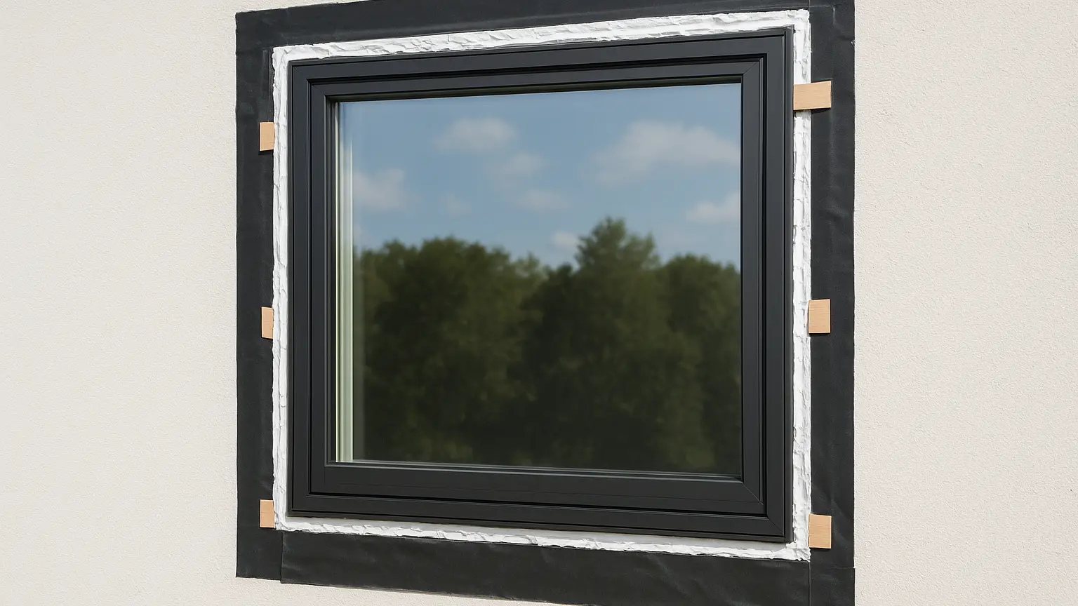
3.1 Continuous Sill Pan Flashing Integration
The foundation of any high-performance Window Flashing and Shim Installation is the rigid or flexible sill pan. Never install a window frame directly onto a flat, un-flashed rough opening sill.
- Rear Dam Elevation: The sill pan must feature a minimum 3/8" (9.5mm) interior rear leg dam to prevent wind-driven water from being forced backward over the sill under negative air pressure.
- End Dams: Both left and right corners of the sill pan require fully sealed end dams (upturned edges) integrated directly into the rough jambs to contain lateral water migration.
- Positive Slope: Slope the rough sill a minimum of 1/4" per foot toward the exterior facade to ensure positive gravity drainage of incidental condensation or leakage.
3.2 Weatherboard (Shingling) Sequence Protocol
Whether utilizing rigid aluminum drip edges, flexible rubberized asphalt membranes, or butyl flashing tapes, installers must execute the four-stage shingling sequence:
- Stage 1 (Bottom Sill): Apply the sill flashing membrane across the sloped rough opening sill, extending it at least 6 inches up each jamb and lapping down over the exterior WRB.
- Stage 2 (Side Jambs): Install vertical jamb flashing membranes over the window mounting flanges or jamb substrates, extending past the sill flashing lower edge.
- Stage 3 (Head Flashing): Install continuous rigid head flashing (drip cap) extending past jamb edges. Lap the upper WRB membrane *over* the head flashing leg to form a complete shingled shed.
- Stage 4 (Air Seal Interior): Apply a continuous bead of low-expansion polyurethane insulating foam or elastomeric air-seal tape between the frame interior and rough framing.
4. Product Recommendations: Custom Metal Window Assemblies Built for Flashing Integration
The Metal Window engineers precision architectural aluminum windows specifically designed to streamline perimeter flashing, shimming, and weatherproofing on commercial job sites. Built exclusively from extruded 6063-T6 alloy with continuous sigma-welded frame corners, our units eliminate joint movement and frame distortion during hoisting and setting.